|
|
|
|
|
|
|
|
|
|
 | Model Design |
|
|
Contents of this page
|
|
|
|
Top_________________________Next
|
Introduction
|
 |
This section deals with design issues. It is primarily written for computer scientists. However, ecologists with at least basic knowledge of UML diagrams, in particular, and of object-oriented programming, in general, may also profit from reading this section.
|
|
|
I do not intend to provide you with a single UML class diagram of the whole model. Following advices of Evans (2004) I will rather highlight important design aspcets with the help of UML package diagrams, class diagrams and state charts, repsectively.
|
|
Code metrics
|
|
|
Code Metrics provide a readily understandable summary of a software product. They are easily obtained with the likewise-named plugin in ECLIPSE. Figure 14 presents code metrics for UIBM.
|
|
|
As of February 2010 UIBM contains 16,616 lines of code. However, in order to get a more meaningful number I translated this to 404 Din A4 pages, assuming 40 lines per page. This appears to be a quite substantial amount of code.
|
|
|
The code is located in 31 packages. It consists of 24 interfaces and 203 classes with 593 attributes and 1775 methods.
|
|
|
|
|
|
|
Top_________________________Next
|
Layered architecture
|
|
|
Inspired by Eric Evans's book "Domain-dirven Design" (Evans 2004) we extended the ABM framework, whose architecture is traditionally two-layered (model and visualization layer), further by the infrastructure and domain layer. Moreover, the model layer was renamed according toEvans (2004) and became the application layer.
|
|
|
Thus, UIBM now has a four-layered archtiecture, which is shown in Figure 15. In principle, direct information flow therein is always from a lower to one of the upper layers.
|
|
|
In fact, the infrastructure layer is at the bottom. It contains various utility methods that are referenced and used by any of the upper layers. Java property files holding model and species-specific paramerters can be found in this layer. The navigation class, which is responsible for the entire navigation in three-dimensional space, is an important component of this layer.
|
|
|
The domain layer is located above the first one. It hosts objects of categorized model and species parameters. Besides that, it sonsists of classes defining plant structure and function as well as classes describing the environment.
|
|
|
The third layer is the application layer. It basically contains several agent classes. The two- or three-dimensional agents, in principle, allow for the interaction of plant components with their environment. The UIBM model class resides in this layer, too.
|
|
|
The topmost layer is the visualization layer. It covers the model visualizaiton class UIBM_withUI and varous classes defining the shape of the visualized structural plant components.
|
|
|
|
|
|
|
Top_________________________Next
|
The AgentManager as puppet master
|
|
|
The AgentManager class plays a crucial role in the communication between domain and application layer. It was necessary to introduce this kind of class as a consequence of adding the domain layer. Figure 16 contains an UML class diagram elucidating its functioning as well as its relationship to other classes.
|
|
|
The AgentManager class implements a "multiton" design pattern. For each of the number of databases set in the UIBM model class an AgentManager singleton is created. Each AgentManager holds a reference to the UIBM model class, which itself extends the SimState superclass. By this reference AgentManager instances have access to UIBM's discrete event Schedule as well as to its various 2d- and 3d-fields. Besides that, an AgentManager holds an AgentContainer hashmap with an AgentContainer instance for each agent type.
|
|
|
During its creation an AgentManager puts its own refill() method first and its clearOut() method last sinto the Schedule's stepping sequence. In between those two methods the AgentManager puts the AgentContainers in an appropriate sequential order to accomplish structured plant action.
|
|
|
Moreover, the AgentManager is part of an observer pattern. While the AgentManager implements the Observer interface, all plant components extend the Observable superclass.
|
|
|
Seeds, which are created at the start of the simulation, are provided with their observer, i.e. the AgentManager, within the UIBM class. Likewise, in that case the notifyObservers() method is called on the Seed instance from the outside in roder to let the AgentManager add a SeedAgent to the seed.
|
|
|
In all other cases a parent plant component, for instance an active internode meristem growing a new internode, notifies its AgentManager observer of the new component, while it is added as a child to the parent component. The AgentManager then takes further action: It adds itself as Observer to the new plant component, adds the component to an agent of the required type and puts the agent into a field at the correct location. By this means addition of agents keeps going on automaically while plants are growing.
|
|
|
In order to make the whole concepts understandable,the puppet master / marionette metaphor is used in Figure 16. You may think of the plant component as part of a marionette, which is moved by the puppet master, the AgentManager, via the wires (i.e. the agent) and the control bar (i.e. the AgentContainer).
|
|
|
|
|
|
UIBM simulates vegetation dynamics on 16m⊃2;, which resembles a grassland-specific Braun-Blanquet mimimum area, where one can find 90% of all species held by a huge homogeneous grassland vegetation of the same kind.
|
|
|
Simulating those dynamics in agent-based manner is likely to represent a challenge due to the large number of objects to be computed at each time step. According to own computations the smallest Arrhenatherum elatius ramet, which develops with minimal nitrogen supply, has a dry mass of 1.295g when it starts flowering. Figure 4-8 in "Terrestrial Plant Ecology" (Barbour et al. 1999) contains a log-log plot of plant mass vs. plant density for the plant reign. Measuring the linear relationship at the upper margin of the point cloud revealed the "two-third power" self-thinning rule to be at maximum:
|
|
|
lg density (no./m⊃2;) = -0.599 x lg dry mass (g) + 4.014.
|
|
|
For the Arrhenatherum ramet given above we end up with a maximum estimated density of 8840 ramets per m⊃2; and 141,440 ramets per 16 m⊃2;, respectively. Given that each ramet possesses 6 internodes and 5 leaves each with 7 planar leaf areas object numbers to be manipulated in UIBM are truly vast.
|
|
|
In order to tackle related heap space problems we added a persistence layer to the model. Vertical layers of the community with a fraction of the plants are processed consecutively and the others are held in databases.The offset between those steps is almost negligible, so that the whole community is virtually processed at the same simulation time. At each step an AgentManager gets an environmental field from the database of its IDatabaseManager, removes all agents from the current UIBM environment and refills it from the database. Since many of the linkages between database and UIBM objects break during serialization, those have to be tied again during field and AgentContainer refillmentt. Then the AgentManager invokes the plant components to perform their action. At the end a copy of the field with all its updated objects is set to the database and the control is passed to the next AgentManager.
|
|
|
Once again you may think of the AgentManager being a puppet master: He gets marionettes (i.e. plant components) with wires (i.e. agents) and control bars (i.e. AgentContainer) from a cupboard (i.e. the database), but before he can manipulate the puppest in the theater he has to substitute control bars and wires, respectively. This metaphor, in fact, is shown on the left-hand side of Figure 16.
|
|
|
|
|
|
|
Top_________________________Next
|
Ramet growth
|
|
|
Figure 17 shows a UML-diagram of the main classes which are associated with ramet growth. In this context the AttributesServiceFacade class plays an important role. This class implements the facade design pattern and delegates all requests for the computation of structural attributes to more specialized service objects, though.
|
|
|
Each day a ramet acquires resources consisting of carbon gained by leaf and internode photosynthesis and nitrogen taken up from the soil by fine roots, respectively. Note, that true functioning of fine roots is not implemented yet. However, the user is able to choose rnitrogen in the resources over the range of maximum/minimum C/N ratios.
|
|
|
At the first full hour after sunrise of the next day the ramet requests from the AttributesServiceFacade the computation of the PartitioningPattern, i.e. the carbon/nitrogen to be partitioned to each organ. The Facade calls the respective method of the specialized PartitioningPatternSevice. The computation, in principle, is dependent on the C/N-ratio in the acquired resources. When resources are poor in nitrogen a larger portion of the resources is likely partitioned belowground.
|
|
|
The ramet then calls AttributesServices for leaves/internodes via the facade to compute organ structural attributes on the basis of the nitrogen concentration in the partitioned resources.
|
|
|
In case the comparison of the carbon amounts available in the PartitioningPattern succeeds amounts required for organ production a new organ set comprising a fine root object, a cloonal growh organ and one or more leaves and internodes is produced in the ramet grow() method.
|
|
|
For the InternodeWithMeris this is basically done by calling the growOrgan() method of active InternodeMeristems. Once again, the structural attributes of the new InternodeWithMeris are computed by a call on the InternodeAttributesService via the facade. Leaves are processed in a similar way.
|
|
|
|
|
|
|
Top_________________________Next
|
Ramet states
|
|
|
Structural attributes of newly-created organs vary with the ontogentetic stage of the growing ramet. In object-oriented programming the state design pattern is used to let the computer-generated versions resemble stage-dependent behaviour of the real-world objects. Hence, in UIBM the Ramet owns an AbstractRametState instance variable, which is assigned to one of several concrete states during different ontogenetic stages. The state classes, in general, do not have instance variables and therefore are never instantiated. All package-wide class methods get the calling Ramet passed in as a parameter.
|
|
|
A UML state chart displaying the sequence of states a ramet seizes during its ontogeny is contained in Figure 18.
|
|
|
After seed germination the ramet enters the seedling state. It does exit this state with the production of one (monocotyledonous species) or two cotyledons (dicotyledonous species), a (base) fine root object and eventually a (base) coarse root object.
|
|
|
The state the ramet enters afterwards, is the VegetativeRametState. The organ sets produced during this state consist of a fine root object, eventually of a coarse root object, a clonal growth organ element, one internode or several internodes after branching and a species-specific number of leaves and meristems at each node.
|
|
|
Whenever the clonal growth organ has grown by a species-specific length, the ramet to wchich it belongs enters the VegetativeReproudcitonState and produces a daughter ramet at the terminal end of the clonal growth organ. Immediately after the vegetative reproduction it returns to its previous state, albeit the VegetativeRamet or the GenerativeRamet state.
|
|
|
When a ramet in VegetativeRametState has acquired a sufficient amount of carbon and/or when the flowering period given in the databases is almost reached, the ramet enters the GenerativeRametState. This brings about a change of the apical meristem typefrom from a primary internode meristem to a primary flower meristem. The state, hower, is left after one internode with its meristem is built.
|
|
|
The state hat follows in the sequence is the CreatePollenState. Pollen is produced until its number arrives at the maximum species-specific maximum.
|
|
|
The finale state of the ramet's determinate growth is the CreateSeedsState, which once again is maintained until the species-specific maximum number is reached.
|
|
|
|
|
|
|
Top_________________________Next
|
Communication among components: Composite pattern
|
|
|
UIBM uses two patterns, which allow plant components to communicate with each other.
|
|
|
The first is the composite pattern, whose UML class diagram is shown in Figure 19.
|
|
|
The composite pattern treats the plant as a tree-like structure of AbstractPlantComponents.
|
|
|
In principle, two types of AbstractPlantComponents are distingueished: AbstractPlantComposite objects have child components, whereas AbstractPlantLeaf objects do not have these components. The latter are situated at the terminal ends of the structure, though.
|
|
|
The superclass AbstractPlantComponent owns an abstract getChildIterator() method, which is overridden in the subclasses. While the AbstractPlantComposite method returns a true CompositeIterator, the same method in the AbstactPlantLeaf subclass does merely return an empty NullIterator.
|
|
|
By this means, the pattern, in principle, allows to treat all components in the same way irrespective of the subclass to whcih they beong.
|
|
|
In UIBM the composite pattern is used in many organ growth and death-related methods.
|
|
|
The search for active meristems performed by the ramet makes usage of the composite pattern.
|
|
|
It is further used in methods for the coordinated removal of the connected plant components comprising the stem. For instance, when the vegetation is mown at a height of 7 cm above grouund, only the lowest internodes are likely to be affected directly by this management event. However, UIBM has to ensure that all plant coponents wich are connected to the lowest internodes but are located above them, are removed by the mechanism as well. Further, while individual internodes are added to the stem during growth, the stem is a functional unit lateron and becomes dead or senescent as a whole late in ontogeny. In fact, all of these functions are accomplished with the composite pattern.
|
|
|
The composite pattern will certainly play an impoortant role in the implementation of the mass transport of water from the soil to the transpiring organs (internodes, leaves), as well.
|
|
|
While the classic composite pattern as described above allows for a parent -> children communiction via iterators, the getParent() method contained in the superclass is suffienet for child -> parent communication, since each child has only one parent component.
|
|
|
However, Figure 19 gives also an overview of all plant components that UIBM distuinguishes. The clonal plant holds the highest catgegory. The clonal plant is defined as a group of ramets that has been vegetatively proudced by a mother ramet. In contrast to the ramet network, the ramets of the clonal plant are not required to have clonal growth organ connections and shared carbon storage. These attributes differentiate the two. About 5 years after seed germination, the death of the clonal growth organ elements commences, the clonal plant begins to break apart and subsequently forms more and more ramet networks.
|
|
|
Apart from the carbon storage that is shared with others the ramet is considered to act autonomously and to be the individual within the Universal Individual-Based Model, though.
|
|
|
The ramet holds mersitems of numerous types as well as a number of vegetatie organ types. While the meristems irrespective of their type are always concrete objects of the AbstracPlantComposite, several of the other componenets are AbstractPlantLeaf objects. LeafArea, Pollen, Seeds CoarseRoots and FineRoots objects are components of this type (compare Figure 19).
|
|
|
|
|
|
|
Top_________________________Next
|
Communication among components: Observer pattern
|
|
|
The observer pattern is the second design pattern that accomplishes component communication. An UML class diagram of the pattern is shown in Figure 20.
|
|
|
Lower category components, such as vegetative organs, use this pattern to report their carbon supply or demand to the ramet. Likewise ramets manage sharing of the carbon storage within the ramet network.
|
|
|
With the observer pattern this many-to-one communication is performed in a fast and decoupled manner.
|
|
|
|
|
|
|
Top_________________________Next
|
Virtual gas exchange experiments
|
|
|
Basically, the following Figure 21 serves three purposes:
|
|
|
(1) The code fragment given in the figure contains an example of how a user can conduct a virtual experiment within UIBM.
|
|
|
(2) The fragment shall make the interaction between applicaion and domain layer clearer.
|
|
|
(3) And finally, the code shall affirm how self-explanatory and readable object-oriented code is.
|
|
|
The code fragment is taken from the step() method of the LeafAreaAgent. This kind of agent holds a LeafArea instance as its plant component.
|
|
|
The method in question does only execute, when an initial check has verified that the underlying LeafArea object has nneither become senescent or dead.
|
|
|
After the user has clicked the LeafAreaAgent in the virtual 3d-world, its inspector GUI opens in the "Inaspector" model console window. Therein, the user can mark the Agent for conducting a virtual gas exchange experiment as an experimental ecologidst would do on the real world leaf. Whether the inspector has been marked by the user is checked in the next line of code. If he wishes to conduct the experiment, the AtmosppericEnvironmentLayer of the LeafArea is replaced with a copy of the AtmopshericEnvironment which could be modified by the user via the model console.
|
|
|
However, we do not let the LeafArea itself do photosynthesis or maintenance respiration. Instead we use a process-specific singleton visitor object to perform the photosynthetic/respiratory calculations. A Photosynthetic- or RespiratoryAttributesService object gets the leaf area attributes necessary for the calculations. The atmospheric environment and a layer-dependent illumination probability (in case of photosynthesis) as well as the simulation time step length are also passed in to the Phtosynthetical- or RespiratoryAttributesService-owned accept() method.
|
|
|
Inside gas exchange calculations the serializable observer, i.e. the ramet, gets the acquired carbon resources reported. The carbon resources tranlocated to the ramet is available for further growth at the follwing morning hour.
|
|
|
|
|
|
|
Top_________________________Next
|
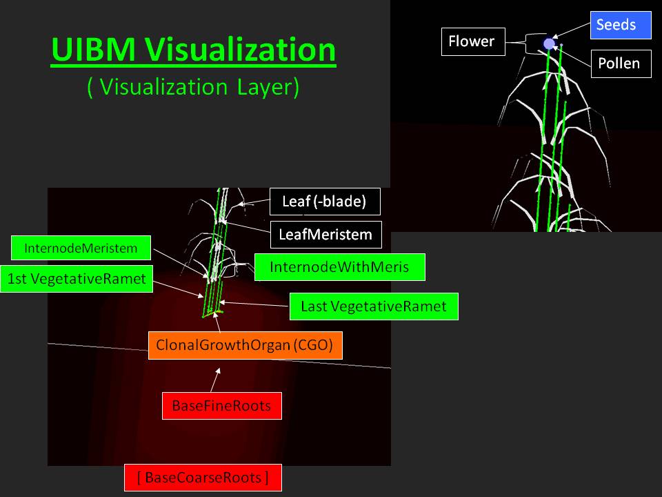
UIBM 3d-visualization
|
|
|
As Figure 22 shows most polant components in UIBM are visualized in 3d by simple geometrical objects. Spheres are used for the 3d-visualization of pollen, seeds, fine root objects and all kinds of meristems, whereas internodes, clonal growth organ elements and the rooting system are displayed as cylinders.
|
|
|
Leaves, however, represent an exception from this procedure. They possess a more complex geometry and leaf shapes were thus built with the Blender tools for 3d creation.
|
|
|
Nonetheless, a portrayal of any kind is assigned to a specific agent type and obtains its size and orientation from the structural attributes of the underlying plant component.
|
|
|
|
|
|
|
Top_________________________Next
|
UIBM 2d-visualization
|
|
|
The general rules outlined in the previous paragraph for 3d-visualization apply also for 2d-display.
|
|
|
Figure 23 shows an examplary 2d-display of a single Arrhenatherum elatius plant after vegetative reproduction has taken place for some time, but separation into ramet networks due to senescence of clonal growh organs has not commenced yet. At his point in simulation time the clonal plant and the ramet network have identical shapes and their representation in 2d, i.e. an unfilled rectangle surrounding the associated ramets, overlaps exactly.
|
|
|
The ramets, however, are visualized in 2d as green circles whose size and color intensity rise with increasing ramet dry mass.
|
|
|
|
|
Navigator
|
You are here: Model Design -> UIBM Development -> Home
Local Navigator: ΛTop <- Previous -> Next
Sub-Page Navigator: Project Aim & Objectives <- Model Design -> Model Parametrization
Whole-Page Navigator: Home -> Background -> UIBM Development <- Virtual Experiments <- Outlook: Virtual Ecology
|
Copyright © Mar. 2010 Dr. U. Grueters
|
|
|
Printable Version
|
|
|
|
|
|
|
|